Contact information

 Close
Close
Close
Close

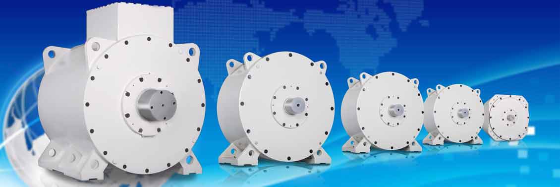
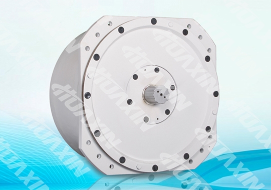
The rated capacity of the Explosion-Proof Variable-Frequency Permanent Magnet Synchronous Motor (The TBVF Series) and the Explosion-proof Low Frequency Permanent Magnet Three-phase Synchronous Motor (The TBD Series) is 55 to 630kW. Compared with the traditional electrically excited motors, the rotor of the motor has a permanent magnet structure (Hereinafter referred to the “Permanent Magnet Motor”), the slip ring and brush gear can be saved. The advantages of the permanent magnet motor include but are not limited to: simple structure, reliable operation, small size, low consumption, high efficiency. The permanent magnet motor adopts the VFD to control synchronous start, which can reduce impact on the electricity grid network, and balance power while operating multiple machines.
Huaxin company is the first manufacturer who develops, obtains patents, and produces explosion-proof permanent magnet motors in China. This series of products have already been sold in many coal companies in Shanxi, Shandong, Gansu, Heilongjiang, Inner Mongolia and other provinces in China.
Specification and Type | Rated Power (kW) | Rated Voltage (V) | Rated Current (A) | Rated Torque (N.m) | Rated Rotating speed (r/min) | Rated Frequency (Hz) | Efficiency (%) | Power Factor |
TBVF-55/24YC(660) | 55 | 660 | 53 | 6734 | 78 | 15.6 | 93 | 0.92 |
TBVF-55/24YC(1140) | 55 | 1140 | 37 | 6734 | 78 | 15.6 | 93 | 0.92 |
TBVF-75/24YC(660) | 75 | 660 | 105 | 9182 | 78 | 15.6 | 93 | 0.92 |
TBVF-75/24YC(1140) | 75 | 1140 | 54 | 9182 | 78 | 15.6 | 93 | 0.92 |
TBVF-110/32YC(660) | 110 | 660 | 135 | 13468 | 78 | 20.8 | 93 | 0.92 |
TBVF-110/32YC(1140) | 110 | 1140 | 74 | 13468 | 78 | 20.8 | 93 | 0.92 |
TBVF-132/32YC(660) | 132 | 660 | 155 | 16162 | 78 | 20.8 | 93 | 0.92 |
TBVF-132/32YC(1140) | 132 | 1140 | 86 | 16162 | 78 | 20.8 | 93 | 0.92 |
TBD-560S-32Y(660) | 160 | 660 | 186 | 19590 | 78 | 20.8 | 93 | 0.92 |
TBD-560S1-32Y(1140) | 160 | 1140 | 115 | 19590 | 78 | 20.8 | 93 | 0.92 |
TBVF-200/32YC(660) | 200 | 660 | 205 | 23151 | 82.5 | 22 | 93 | 0.92 |
TBVF-250/32YC(660) | 250 | 660 | 255 | 28939 | 82.5 | 22 | 93 | 0.92 |
TBD-560L1-32Y(1140) | 250 | 1140 | 184 | 28939 | 82.5 | 22 | 93 | 0.92 |
TBD-630S-32Y(1140) | 315 | 1140 | 186 | 37370 | 80.5 | 21.5 | 93 | 0.92 |
TBD-630M-32Y(1140) | 355 | 1140 | 205 | 42115 | 80.5 | 21.5 | 93 | 0.92 |
TBD-630L-32Y(1140) | 400 | 1140 | 224 | 47453 | 80.5 | 21.5 | 93 | 0.92 |
TBVF-400/40YC(1140) | 400 | 1140 | 270 | 44418 | 86 | 28.7 | 93 | 0.92 |
TBVF-450/40YC(1140) | 450 | 1140 | 287 | 49971 | 86 | 28.7 | 93 | 0.92 |
TBVF-500/40YC(1140) | 500 | 1140 | 305 | 55523 | 86 | 28.7 | 93 | 0.92 |
TBVF-560/40YC(1140) | 560 | 1140 | 378 | 62186 | 86 | 28.7 | 93 | 0.92 |
TBVF-630/40YC(1140) | 630 | 1140 | 387 | 69959 | 86 | 28.7 | 93 | 0.92 |
Specification and Type | Range of Speed Regulation (r/min) | Number of Poles | Protection Level | Explosion- Proof Label | Insulation Class | Cooling Mode | Working System | Total Weight (kg) |
TBVF-55/24YC(660) | 0~78 | 24 | IP55 | EXDI | H | IC46W | S1 | 1320 |
TBVF-55/24YC(1140) | 0~78 | 24 | IP55 | EXDI | H | IC46W | S1 | 1320 |
TBVF-75/24YC(660) | 0~78 | 24 | IP55 | EXDI | H | IC46W | S1 | 1950 |
TBVF-75/24YC(1140) | 0~78 | 24 | IP55 | EXDI | H | IC46W | S1 | 1950 |
TBVF-110/32YC(660) | 0~78 | 24 | IP55 | EXDI | H | IC46W | S1 | 2400 |
TBVF-110/32YC(1140) | 0~78 | 24 | IP55 | EXDI | H | IC46W | S1 | 2400 |
TBVF-132/32YC(660) | 0~78 | 24 | IP55 | EXDI | H | IC46W | S1 | 2700 |
TBVF-132/32YC(1140) | 0~78 | 24 | IP55 | EXDI | H | IC46W | S1 | 2700 |
TBD-560S-32Y(660) | 0~78 | 32 | IP55 | EXDI | H | IC46W | S1 | 3400 |
TBD-560S1-32Y(1140) | 0~78 | 32 | IP55 | EXDI | H | IC46W | S1 | 3400 |
TBVF-200/32YC(660) | 0~82.5 | 32 | IP55 | EXDI | H | IC46W | S1 | 3600 |
TBVF-250/32YC(660) | 0~82.5 | 32 | IP55 | EXDI | H | IC46W | S1 | 4100 |
TBD-560L1-32Y(1140) | 0~82.5 | 32 | IP55 | EXDI | H | IC46W | S1 | 4100 |
TBD-630S-32Y(1140) | 0~80.5 | 32 | IP55 | EXDI | H | IC46W | S1 | 6140 |
TBD-630M-32Y(1140) | 0~80.5 | 32 | IP55 | EXDI | H | IC46W | S1 | 6300 |
TBD-630L-32Y(1140) | 0~80.5 | 32 | IP55 | EXDI | H | IC46W | S1 | 6900 |
TBVF-400/40YC(1140) | 0~86 | 40 | IP55 | EXDI | H | IC46W | S1 | 6900 |
TBVF-450/40YC(1140) | 0~86 | 40 | IP55 | EXDI | H | IC46W | S1 | 7400 |
TBVF-500/40YC(1140) | 0~86 | 40 | IP55 | EXDI | H | IC46W | S1 | 8000 |
TBVF-560/40YC(1140) | 0~86 | 40 | IP55 | EXDI | H | IC46W | S1 | 8900 |
TBVF-630/40YC(1140) | 0~86 | 40 | IP55 | EXDI | H | IC46W | S1 | 9900 |
Compared with the traditional AC Asynchronous Motor, the Permanent Magnet Motor has the following advantages:
1.High Efficiency. It can be indicated from four aspects:
(1) The magnetic field of the Permanent Magnet Synchronous Motor is generated by the permanent magnet, so as to avoid loss of excitation caused by magnetic field generated from the excitation current (copper loss);
(2) Compared with the external characteristic efficiency curve of the Asynchronous Motor, the Permanent Magnet Synchronous Motor has higher efficiency value at light load, which is the greatest advantage of the Permanent Magnet Synchronous Motor than the Asynchronous Motor in the aspect of energy saving. The motor rarely operates at full load when driving load, and the reasons are: on the one hand, the user determines the motor power according to the limit conditions of the load during motor selection. However, the opportunity of limit condition is rare. Meanwhile, in order to prevent motor burns at the abnormal condition, the user will also further reserve the allowance for the motor; on the other hand, when the designer designs the motor, in order to guarantee the motor reliability, a certain power allowance will be further reserved based on the power required by the user. It causes that over 90% motors in actual operation work below 70% of the rated power, especially when driving fans or pumps, which causes that the motors usually work in the light load area. The Induction Motors have low efficiency at light load. However, higher efficiency of the Permanent Magnet Synchronous Motors can still be maintained in the light load area, and the efficiency is higher than that of the Asynchronous Motors by over 20%.
(3) Based on the reason given in the Article 2 above, the power factor of the Permanent Magnet Synchronous Motor is high. Therefore, compared with Asynchronous Motor, the motor current of the Synchronous Motor is lower, the copper loss of the motor’s stator is lower correspondingly, and the efficiency is higher.
(4) High system efficiency: the Permanent Magnet Motor's parameters, especially the power factor, are not influenced by the number of motor poles. Therefore, it is convenient to be designed as multi-pole motor (such as over 100 poles). In the traditional way, the load motor should be driven by the Speed Reducer. However, it can be made into a direct drive system that is driven by the Permanent Magnet Synchronous Motor so as to save the Speed Reducer, and improve the transmission efficiency.
2. High Power Factor
The power factor is adjustable during the designing of the Permanent Magnet Synchronous Motor. The power factor can be designed as 1, and it is unrelated with the number of motor poles. However, due to the excitation features of the Asynchronous Motor, the power factor will be lower and decrease with increasing the number of poles. For example, the power factor of 8-pole motor is usually 0.85. The larger the number of poles is, the lower the corresponding power factor is. Even if 2-pole motor with the maximum power factor, it is difficult for the power factor to reach 0.95. If the motor power factor is high, there are the following advantages:
(1) If the power factor is high, the motor current is low, so as to reduce the copper loss of the motor stator, and more energy is saved;
(2) If the power factor is high, the capacity of the supporting devices of the motor, such as the inverter, transformer, etc, can be lowered. Meanwhile, the specifications of other auxiliary facilities, such as the switch, cable, etc. can be smaller, and the corresponding system cost is lower.
(3) The power factor of the Permanent Magnet Synchronous Motor is not restricted by the number of motor poles. If the motor supporting system permits, the number of motor poles can be designed higher, the corresponding motor volume can be smaller, and the direct material cost of the motor is lower.
3. Simple and Flexible Motor Structure
(1) The conducting bar, end ring and rotor windings shall be installed on the Asynchronous Motor, which greatly restricts the flexibility of the Asynchronous Motor's structure.
(2) The parameters of the Permanent Magnet Synchronous Variable Frequency Speed Control Motor are not restricted by the number of motor poles, so the motor can directly drive the load. The Speed Reducer which has large noise and high failure rate can be eliminated, and the flexibility in mechanical transmission system design can be increased.
(3) Without the restriction by the number of poles, the Permanent Magnet Synchronous Variable Frequency Speed Control Motor can be designed as the multi-pole motor. The number of motor poles is close or equal to the number of slots of the motor, i.e., realizing that the motor pitch (i.e., coil span) is close or equal to 1. Centralized winding can be realized, which can greatly shorten the length of the ends of the 'invalid part' of the motor stator windings, so as to greatly shorten the machine length, and reduce the motor volume. Especially on the occasion with higher requirements for the axial length of the motor, by utilizing the feature of multi-pole centralized winding of the permanent magnet synchronous motor, the motor can be designed as the disc structure, which fully reflects the advantages of the permanent magnet synchronous motor. On the other hand, the winding ends are greatly reduced, and the copper loss caused by motor winding ends is reduced correspondingly, which further improves motor efficiency.
4. High Reliability
Comparing between the two motors themselves, the reliability of the Permanent Magnet Synchronous Variable Frequency Speed Control Motor is equivalent to that of the Asynchronous Motor. However, due to the flexibility of the Permanent Magnet Synchronous Motor's structure, it is convenient for directly loading the drive and eliminating the Speed Reducer with low reliability, thus greatly improves the reliability of the transmission system.
5. Small Volume and Large Power Density
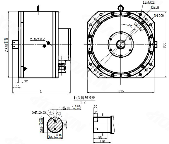
55kW and 75kW Motor Installation Drawing
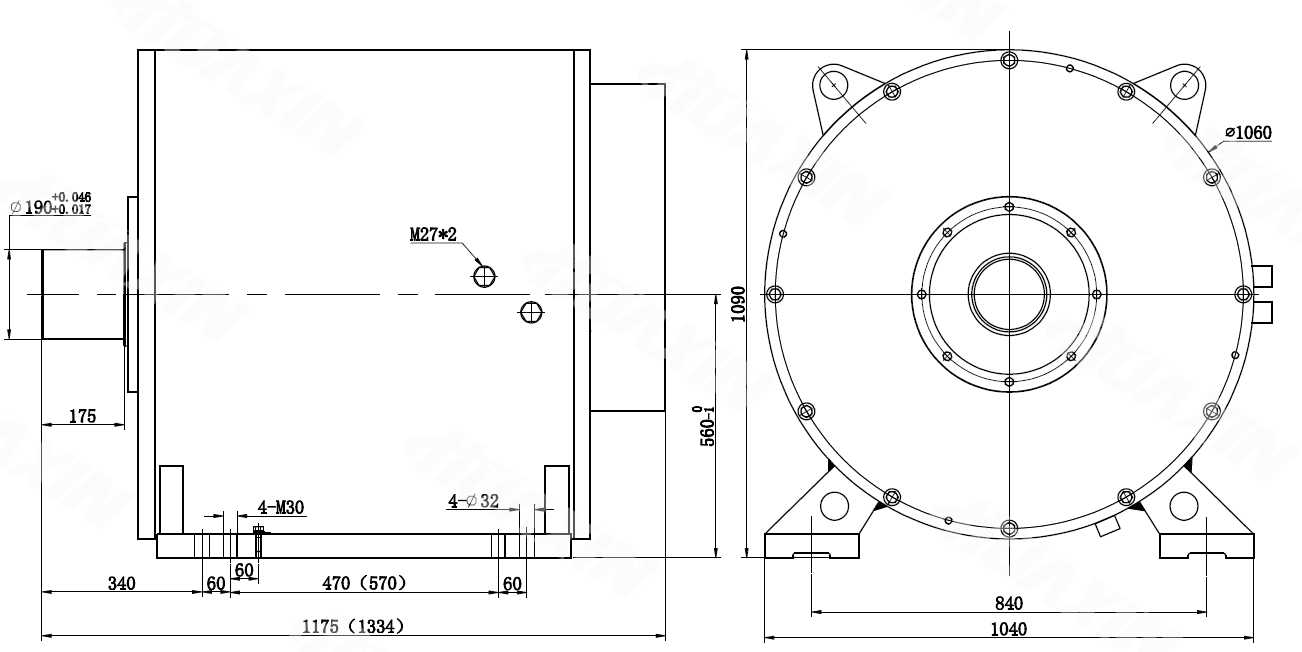
110kW, 132kW, 160kW Motor Installation Drawing
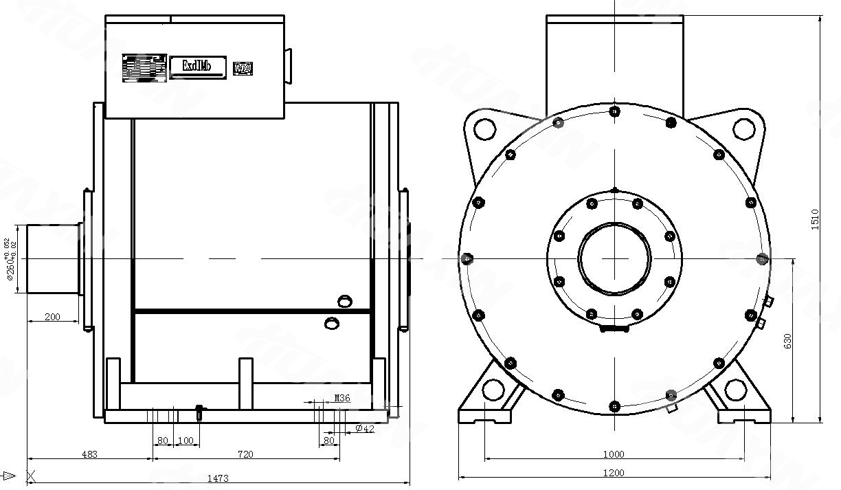
200kW, 250kW Motor Installation Drawing
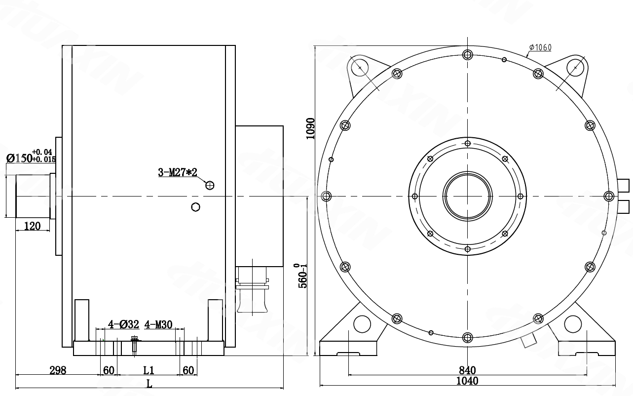
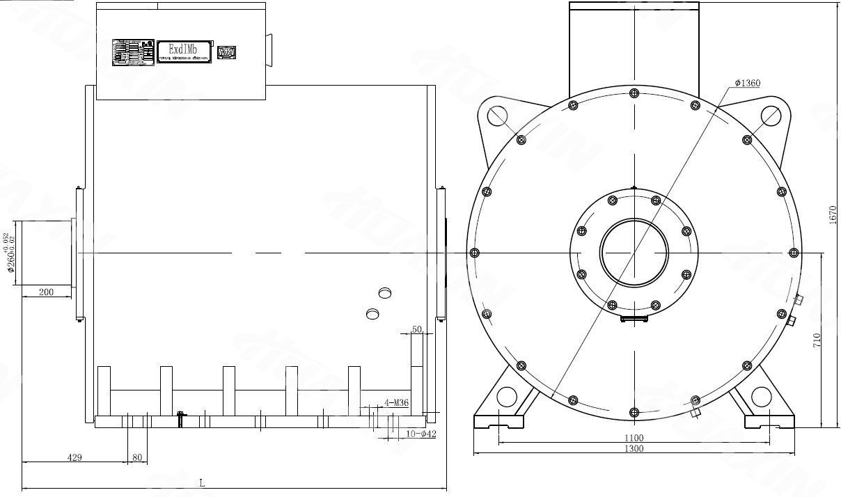
315kW, 355kW, 400kW Motor Installation Drawing
400kW, 450kW, 500kW, 560kW, 630kW Motor Installation Drawing
Table of Selection of Permanent Magnet Motor of Shanxi Huaxin Electric Co., Ltd. | |||||||||
Specification and Type | Rated Power (kW) | Rated Rotating Speed (r/min) | Rated Torque (N.m) | Motor Output Power Corresponding to Different Working Speeds (kW) | |||||
>50-55 r/min | >55-65 r/min | >65-75 r/min | >75-85 r/min | >85-95 r/min | >95-105 r/min | ||||
TBVF-55/24YC(660) | 55 | 78 | 6734 | 39 | 46 | 53 | 55 | 67 | 74 |
TBVF-55/24YC(1140) | 55 | 78 | 6734 | 39 | 46 | 53 | 55 | 67 | 74 |
TBVF-75/24YC(660) | 75 | 78 | 9182 | 53 | 63 | 72 | 75 | 91 | 101 |
TBVF-75/24YC(1140) | 75 | 78 | 9182 | 53 | 63 | 72 | 75 | 91 | 101 |
TBVF-110/32YC(660) | 110 | 78 | 13468 | 78 | 92 | 106 | 110 | 134 | 148 |
TBVF-110/32YC(1140) | 110 | 78 | 13468 | 78 | 92 | 106 | 110 | 134 | 148 |
TBVF-132/32YC(660) | 132 | 78 | 16162 | 93 | 110 | 127 | 132 | 161 | 178 |
TBVF-132/32YC(1140) | 132 | 78 | 16162 | 93 | 110 | 127 | 132 | 161 | 178 |
TBD-560S-32Y(660) | 160 | 78 | 19590 | 113 | 133 | 154 | 160 | 195 | 215 |
TBD-560S1-32Y(1140) | 160 | 78 | 19590 | 113 | 133 | 154 | 160 | 195 | 215 |
TBVF-200/32YC(660) | 200 | 82.5 | 23151 | 133 | 158 | 182 | 200 | 230 | 255 |
TBVF-250/32YC(660) | 250 | 82.5 | 28939 | 133 | 158 | 182 | 200 | 230 | 255 |
TBD-560L1-32Y(1140) | 250 | 82.5 | 28939 | 133 | 158 | 182 | 200 | 230 | 255 |
TBD-630S-32Y(1140) | 315 | 80.5 | 37370 | 215 | 254 | 293 | 315 | 372 | 411 |
TBD-630M-32Y(1140) | 355 | 80.5 | 42115 | 243 | 287 | 331 | 355 | 419 | 463 |
TBD-630L-32Y(1140) | 400 | 80.5 | 47453 | 273 | 323 | 373 | 400 | 472 | 522 |
TBVF-400/40YC(1140) | 400 | 86 | 44418 | 256 | 302 | 349 | 395 | 400 | 488 |
TBVF-450/40YC(1140) | 450 | 86 | 49971 | 288 | 340 | 392 | 445 | 450 | 549 |
TBVF-500/40YC(1140) | 500 | 86 | 55523 | 320 | 378 | 436 | 494 | 500 | 610 |
TBVF-560/40YC(1140) | 560 | 86 | 62186 | 358 | 423 | 488 | 553 | 560 | 684 |
TBVF-630/40YC(1140) | 630 | 86 | 69959 | 403 | 476 | 549 | 623 | 630 | 769 |
The TBVF Series Explosion-Proof Variable-Frequency Permanent Magnet Synchronous Motor and the TBD Series Explosion-proof Low Frequency Permanent Magnet Three-phase Synchronous motor are taken as the power input mechanism, supported by the VFD to form the Permanent Magnet Direct Drive System, which directly drives the belt conveyor.
The TBVF series and TBD series Permanent Magnet Motors can also be taken as the power input mechanism in the mine, petroleum, building materials and other industries.
1. The altitude shall not exceed 1,000m, and it shall be derated for use when exceeding 1,000m;
2. Environmental Temperature: The maximum air temperature changes with the seasons, but shall not be more than 40 ℃(104ºF); The lowest air temperature 0 ℃(32ºF);
3. The cooling Water: the cooling water inlet temperature should be not more than + 25 ℃(+77ºF), also shall not be lower than + 5 ℃(+41ºF). The pressure of cooling water shall be no less than 0.3MPa, no more than 1 MPa, and the flow rate should be no less than 2.8t/h;
4. The maximum relative humidity shall not be more than 95% (25ºC/77ºF)
5. In mines with methanol gas mixture and coal dust and there is explosion danger;
6. The harmonic voltage factor of the power supply shall not exceed 0.02.
Close
Close


©1996-2023 晋ICP备07500050号 Huaxin Copyright


©1996-2023 晋ICP备07500050号 Huaxin Copyright