Contact information

 Close
Close
Close
Close

The PBGY Mining Explosion-proof High-voltage Permanent Magnet Vacuum Power Distribution Device is mainly used in the coal mine with explosive hazardous gas (methane mixture) for control, protection and measurement of the power supply system with three-phase AC neutral point indirectly grounded with rated voltage of 10KV and 6KV, rated frequency of 50Hz, rated current to 630A. The device has the functions of insulation monitoring, high voltage leakage, short circuit, overload, undervoltage, overvoltage, and overvoltage absorption; it has functions such as tile blocking, remote power off and analog fault testing, etc. It is especially suitable as a distribution in central or mining areas. Electric switch can also be used to direct control high voltage motor.
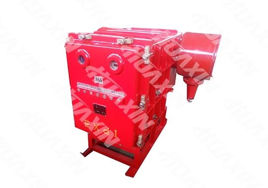
Good explosion-proof performance, advanced technologies, stable and reliable protection performance, compact structure, easy for maintenance and overhaul. The Power Distribution Device adopts a technologically advanced intelligent multifunctional comprehensive protector, which has a more reliable and sensitive protection and higher measurement accuracy. Combining with the Chinese menu human-computer interaction, the display information is richer, and operation is simpler and more intuitive.
Technical Parameters
1. Rated parameters of the complete machine
1.1 Rated Operating Voltage: 10KV, 6KV
1.2 Rated Current: 6KV: 50A, 100A, 200A, 315A, 400A, 500A, 630A
10KV: 50A, 100A, 200A, 315A, 400A, 500A, 630A
1.3 Rated Frequency: 50Hz
1.4 Rated Short-circuit Breaking Current 12.5KA (effective value)
1.5 Rated Short-circuit Making Current 31.5KA (peak value)
1.6 Rated Dynamic Stability Current (rated peak withstand current) 31.5KA (peak value)
1.7 Rated Thermal Stability Current (rated short-time withstand current) 12.5KA (effective value)
1.8 The rated thermal stability (short-term withstand) time is not less than 2s
1.9 The breaking frequency of the rated short-circuit breaking current is 30 times. For operation sequence, see Table 1
Table 1
Serial No. | Short-circuit Breaking Current Percentage % | Operation Sequence | Test Frequency |
1 | 10 | O-180s-CO-180s-CO | 1 |
2 | 30 | O-180s-CO-180s-CO | 1 |
3 | 60 | O-180s-CO-180s-CO | 1 |
4 | 100 | O-180s-CO-180s-CO | 2 |
5 | 100 | O | 13 |
6 | 100 | CO | 11 |
1.10 For rated insulation level, see Table 2
Rated Voltage | Short-time (1min) Industrial Frequency Withstand Voltage Value (effective value) kW | Remarks | |||
Ground, phase, circuit breaker fracture | Isolation Switch Fracture | Secondary circuit to ground | Secondary circuit withstand voltage shall be disconnected, various instrument and display device | ||
6 | 30 | 34 | 2 | ||
10 | 42 | 48 | 2 | ||
Rated Full-Wave Lightning Impulse Withstand Voltage (Peak) KV | |||||
Ground, phase, circuit breaker fracture | Isolation Switch Fracture | ||||
60 | 70 | ||||
75 | 85 | ||||
1.11 For voltage level, electrical clearance and creepage distance, see Table 3
RatedVoltage V | Minimum Electric Clearance mm | Minimum Creepage Distance mm |
100 | 2.5 | 4 |
6000 | 60 | 100 |
10000 | 100 | 160 |
2 For main technical parameters of the circuit breaker, see Table 4
Name | Parameters | Unit |
ZN-12/630-12.5 | ||
Contact Distance | 9±1 | mm |
Contact Over Travel | 3+1 | mm |
Contact Closing Bounce | ≤3 | ms |
Three-phase Different Period | ≤1 | ms |
Average Closing Speed | 0.6-1.3 | m/s |
AverageOpening Speed | 0.8-1.5 | m/s |
Main Circuit Resistance | ≤120 | uΩ |
Contact Pressure | ≥930 | N |
Mechanical Life | 10000 | Time |
3. The supporting JSZW3-6, 10 voltage transformer is three-phase five-column type. The basic technical parameters are shown in Table 5
Model | RatedVoltage (V) | AccuracyClass and Corresponding Rated Load (VA) | Limit output (VA) | |||||
Primary Winding | Secondary Winding | Residual winding | 0.5 | 1 | 3 | 6P/3P | ||
JSZW3—6 | 6000√3 | 100/√3 | 100/3 | 120 | 150 | 300 | 120 | 600 |
JSZW3—10 | 10000√3 | 150 | 240 | 300 | 120 | 600 | ||
4 The supporting LMZ-6, 10 bi-polar current transformer is divided into the signal source and the current source winding.
The current source winding meets the requirements of Table 6
Rated Primary Current (A) | Rated Secondary Current (A) | Rated Load (VA) | Accuracy Class | Accurate Limit Value Coefficient |
50 | 5 | 3.75 | 3 | 6 |
100, 200, 315 400, 500, 630 | 5 | 3.75 | 3 | 10 |
The maximum output power of the current source winding shall not be less than 25VA, that is to say, when the primary passes through over 4 times of the rated current, and the secondary is connected with 25Ω (COSΦ=1) load, the secondary current shall not be less than 1A.
5 Integrated protection of the high-voltage switch has electric leakage, short circuit, overload, under-voltage, overvoltage, insulation monitoring and other protection functions, and the specific indicators are as follows:
5.1 Rated Supply Voltage of Relay Protection
The rated supply voltage of relay protection shall be AC 100V (50Hz), the power consumed shall not be larger than 30VA, and it shall reliably work within the range of 75%~120% rated voltage.
5.2 Overcurrent Protection
The inverse time limit characteristics of overcurrent and delay time shall conform to Table 1:
Table I: Table of Overload Inverse Time Limit
Time Delay Period Overload Current | Setting Position | |||
1 | 2 | 3 | 4 | |
1.05×Ie | ∞ | ∞ | ∞ | ∞ |
1.20×Ie | 40"-60" | 60"-2’ | 2’-3’ | 3’-6’ |
1.50×Ie | 20"-40" | 30"-60" | 1’-1’30" | 1’30"-2’30" |
2.00×Ie | 11"-20" | 14"-20" | 20"-40" | 40"-60" |
6.00×Ie | >8" | >8" | >8" | >8" |
Ie represents the rated operating current set on the power distribution device. In case of interrupted overload, inverse time limit protection shall be implemented during release of overload energy and accumulated calculation.
5.3 Short Circuit Protection
The action current of short circuit protection shall be set at discretion according to 1.5-10 times of the rated current value, the error in setting value shall not exceed ±10%, and the short circuit protection action time shall be less than 0.1s.
5.4 Cable Insulation Monitoring Protection
Shielded core wire and shielded bottom wire on the load side of the switchgear shall be used for insulation monitoring and protection. Surveillance of over-limit alarms shall be performed and actions shall be taken. Insulation monitoring may be switched on or off. See Table 2 for the insulation monitoring and protection operating characteristics.
Table 2 Table of Insulation Monitoring Protection Action Characteristics
ProtectionWorking State | Reliable Action | Permissible Action | Action not Permitted |
Loop resistance between the monitoring wire and ground wire | >1.5K | 0.8~1.5K | <0.8K |
Insulation resistance between the monitoring wire and the ground wire | <3.0K | 3.0 to 5.5K | >5.5K |
5.5 Grounding (leakage) Protection
The electric leakage modes for single-phase grounding failure appearing in the electricity grid are: current type, voltage type, power type and direction type.
a. Current type, i.e., the protector only acts based on the zero sequence current. When the zero sequence current in the power grid reaches the setting value, the protector acts.
b. Voltage type, i.e., the protector only acts based on the zero sequence voltage. When the zero sequence voltage in the power grid reaches the setting value, the protector acts.
c. Power type, i.e., the protector must make protection action when the zero-sequence voltage and zero sequence current reach the setting value simultaneously. It will not make action if only one is reached.
d. Direction type, i.e., the protector must make action when the zero-sequence voltage and zero sequence current reaches the setting value, and the phase positions are the same (0-180°).
5.6 Voltage Protection
a. Low Voltage Protection
Reliable protection when the electricity grid voltage is reduced below 75% of the rated value.
Low voltage protection action time ≤5s.
b. Overvoltage Protection
Reliable protection when the electricity grid voltage is reduced over 115% of the rated value.
Overvoltage protection action time ≤5s.
The action value of low-voltage and overvoltage protection can be appointed and preset by the user.
5.7 Power Grid Real-time Voltage Display: Line Voltage (V)
Measuring range: 6KV and 10KV (any display mode can be selected, that is to say, please select 6KV display mode if used on 6KV high-voltage power distribution device). Precision ±8%.
5.8 Phase Balance:
In case of broken circuit of any phase power supply or it is lower or higher than 60% of the load current of other two phases, make protection action after time delay of 5s to 30s. The phase balance function is arranged with a on and off menu, and the user can select on or off freely.
5.9 Gas Blocking:
It is used with the gas power breaker. After the gas power breaker action is output, the power will be turned off and the gas overlimit will be displayed.
5.10 The current electricity grid voltage and load current value are displayed in Chinese character, which can show the causes of the protection action.
5.11 Long-term memory of the trip reason (it can be consulted repeatedly), Previous 100 times failure trip reason and time recording. Failure can be memorized after power off. Up to 100 reasons and time recording for tripping can be stored for long-term (can be reviewed repeatedly), power failure can remember faults.
5.12 It can record the accumulated opening and closing frequency.
5.13 Digital watch function, it can accurately position the off-work time.
5.14 System password function, it prevents operation by the unrelated personnel.
5.15 Intrinsically-safe parameters (not required for the non-communication model)
485 communication output circuit is intrinsically-safe, 485A, 485B and COM three communication signal wire can independently work and form loop without power supply.
1. External Structure (See attached figure I)
(1) The power distribution device consists of an underframe and a rectangular explosion-proof housing. The explosion-proof housing consists of a main chamber, a box door, two rear covers and a rear wiring chamber. The explosion-proof housing has a rectangular solid structure. It is divided into the front and rear chambers with a partition board in the middle, which are the independent explosion-proof parts.
(2) There are six plug static contact bases and two seven-core terminal posts on the middle division (partition) board. The illuminating lamp is installed at the upper left corner of the division board. The rear chamber is a wiring chamber, which is divided into upper and lower chambers (the intermediate insulating baffle does not have the explosion-proof function). The upper chamber is for the power inlet line. The lower chamber is for the load outlet line, the outlet of the high-voltage cable of the lower chamber is installed with a zero sequence current transformer, and compression nut lead-in devices are arranged at the left and right plates, one for each plate(the user can lead out the control line for remote control).
(3) The main chamber is equipped with a handcart type high-voltage vacuum circuit breaker and a subsidiary operating mechanism.. The handcart high-voltage vacuum circuit breaker consists of a vacuum circuit breaker, a trolley, a three-phase five-column voltage transformer, a busbar core-type current transformer, a microcomputer comprehensive protection device, a varistor, and an isolating plug moving contact, etc. The electrical components are installed on the trolley. In case of any failure of the machine core, the trolley can be pulled out of the box, so as to facilitate maintenance or replacing the spare part. The microcomputer comprehensive protection device has overload, short circuit, electric leakage, cable insulation monitoring and other protection functions; it has the current and voltage display functions and the failure type text representation function.
(4) The housing is a quick-release door structure with a hinge bolt and a reliable mechanical locking device (a) There is an electromechanical locking mechanism with load isolation in the right shaft head of the main shaft of the circuit breaker and the rail shield.(see attached figure II). When the isolation pin is at the closed state, and the vacuum circuit breaker is closed, the locking mechanism operates, and the isolation pin cannot be pulled out. (b) The power distribution device also has a locking mechanism for opening and closing the isolation pin (see attached figure III). When opening the box door, power off the vacuum circuit breaker to release locking (see attached figure II), the isolation pin is pulled out, and at this time, the sleeve on the isolation mechanism allows the locking rod to be inserted, the locking rod is screwed out of the screw hole of the container door, and the isolation mechanism sleeve is inserted at the same time, and the isolation pin cannot be connected. When the isolation pin needs to be connected, the locking rod is screwed into the screw hole of the front door, the isolation mechanism sleeve is not restricted, the isolation pin can be inserted, but the box door cannot be opened.. That is to say: After the isolation pin opens into position, the locking rod is screwed out of the screw hole of the front door, and the box door can be opened; after the box door is opened, the isolation plin cannot be connected; after the isolation pin is inserted in place, the vacuum circuit breaker can be closed; the isolating pin cannot be opened or closed with load. The propulsion mechanism installed on the right side of the main chamber is to push forward and retreat the circuit breaker trolley to close and open the isolation latch. Each floor of the main chamber has a shield and a track, and an extension track, which is used for walking the circuit breaker trolley. The right side of the main chamber is also equipped with a circuit breaker manual closing shaft and a manual trip handle. There are observation windows on the left and right side plates on the back side of the main chamber, one for each side plate, and the isolation pin can be seen to be separated.
2. Devices on the Door
There are electrical energy display, Chinese character display and opening/closing status display on the box door for convenient observation. Seven buttons of lighting, start, stop, electric leakage, displacement, confirm and resetting are also arranged.
3. Wiring Schemes of the Main Circuit
There are four kinds of main circuit wiring schemes of the power distribution device according to its function in the system:
Type A: see Figure 1 for the primary wiring scheme. There are two power incoming ends, and the power distribution device can be used separately or in a combined way.
Type B: see Figure 2 for the primary wiring scheme. There is a power incoming end, and the other end is connected with the long sleeve. That is to say, the power supply side is single loop feed in, and the load side is single loop feed out. The power distribution device can be used separately or in a combined way.
Type C: see Figure 3 for the primary wiring scheme. There is a power incoming end, and the other end is sealed with the end cover, i.e., single loop feed in and single loop feed out. The power distribution device can be used separately or as the main switch, and can also be used in a combined way.
Type D: see Figure 4 for the primary wiring scheme. The primary wiring scheme has no incoming end, and the three-phase power is directly connected with the wiring terminal of the switch from the cable line of the adjacent switch. When multiple power distribution devices are combined for use in the chamber, the power distribution device is only taken as the branch switch and can only be used in a combined way instead of being used separately.

The cable heads of the above A, B, and C schemes may be armored or rubber cable heads. The user should specify when ordering. If there is no description, armored cable heads will be used.
4.Electrical Principle
(1). Working principle of the main circuit:
6KV (10KV) three-phase power supply is introduced from the power junction box of the power distribution device. It is output to the load from the curved cable port in the rear chamber through the upper isolating pin, vacuum circuit breaker and lower isolating pin.
Electrical principle (see the electrical schematic diagram)
After the isolating pin is inserted in place, 6KV (10KV) power supply generates three-phase AC 100V voltage by the three-phase five-column voltage transformer through high-voltage fuse FU-G, and supplies power for computer protection and switch through the secondary fuse.
Electric closing circuit: press the QA closing button, the circuit breaker is closed, and the closing lamp is on.
Electric opening circuit: press the TA opening button, the circuit breaker is opened synchronously, and the opening lamp is on.
(2). Protection action opening circuit:
In case of any protection action of overload, short circuit, electric leakage, monitoring, overvoltage, under-voltage, etc, the comprehensive protection device outputs the opening signal, the circuit breaker is opened, and the opening lamp is on.
(3). Manual Opening:
The operator can complete the circuit breaker opening through a manual release device.
Failure of overload, short circuit, electric leakage, monitoring, overload and under-voltage circuit would be automatically handled by the microcomputer. Therefore, in case of any failure, the corresponding Chinese display can be memorized for a long term, and the cause and time records of the first 100 fault trips can be checked repeatedly.
1. Ambient temperature -20℃ / +40℃ (-4ºF to 104ºF);
2.The elevation height shall not exceed 2000m (0.08~0.11MPa);
3. The surrounding relative humidity should not exceed 95% (25ºC/77ºF);
4. Mines with a mixture of methane and coal dust;
5. Places without strong bump, impact and vibration;
6. Places where water dripping and immersion can be prevented;
7. The installation inclination with the horizontal plane shall not exceed 15°.
Close
Close


©1996-2023 晋ICP备07500050号 Huaxin Copyright


©1996-2023 晋ICP备07500050号 Huaxin Copyright