Contact information

 Close
Close
Close
Close

The PBG Mining Explosion-proof High-voltage Vacuum Power Distribution Device is mainly used in the coal mine with explosive hazardous gas (methane mixture) for control, protection and measurement of the power supply system with three-phase AC neutral point indirectly grounded with rated voltage of 10KV and 6KV, rated frequency of 50Hz, rated current to 630A. The device is provided with insulation monitoring, high-voltage electric leakage, overload, phase failure, under-voltage, short circuit, loss of voltage overvoltage absorption and other protection functions; it has wind electricity blocking and gas blocking power-off functions and a simulated failure test function. It is especially suitable as a distribution switch in the central or mining area substation. It can also be used to directly control the high-voltage motors.
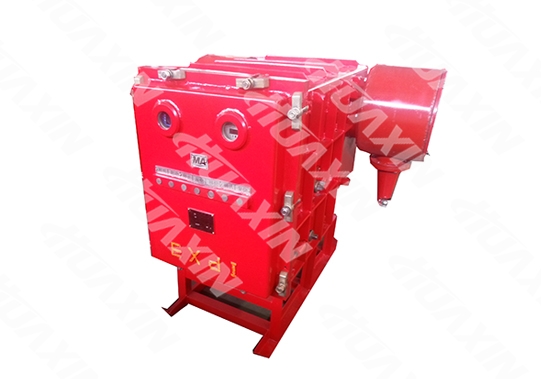
Good explosion-proof performance, advanced technologies, stable and reliable protection performance, compact structure, easy for maintenance and overhaul. The Power Distribution Device adopts a technologically advanced intelligent multifunctional comprehensive protector, which has a more reliable and sensitive protection and higher measurement accuracy. Combining with the Chinese menu human-computer interaction, the display information is richer, and operation is simpler and more intuitive.
1. External Structure (See attached figure I)
(1) The power distribution device consists of an underframe and a rectangular explosion-proof housing. The explosion-proof housing consists of a main chamber, a box door, two rear covers and a rear wiring chamber. The explosion-proof housing has a rectangular solid structure. It is divided into the front and rear chambers with a partition board in the middle, which are the independent explosion-proof parts.
(2) There are six plug static contact bases and two seven-core terminal posts on the middle division (partition) board. The illuminating lamp is installed at the upper left corner of the division board. The rear chamber is a wiring chamber, which is divided into upper and lower chambers (the intermediate insulating baffle does not have the explosion-proof function). The upper chamber is for the power inlet line. The lower chamber is for the load outlet line, the outlet of the high-voltage cable of the lower chamber is installed with a zero sequence current transformer, and compression nut lead-in devices are arranged at both the left and right plates, one for each plate(the user can lead out the control line for remote control).
(3) The main chamber is equipped with a handcart type high-voltage vacuum circuit breaker and a subsidiary operating mechanism.. The handcart high-voltage vacuum circuit breaker consists of a vacuum circuit breaker, a trolley, a three-phase five-column voltage transformer, a busbar core-type current transformer, a microcomputer comprehensive protection device, a varistor, and an isolating plug moving contacts, etc. The electrical components are installed on the trolley. In case of any failure of the machine core, the trolley can be pulled out of the box, so as to facilitate maintenance or replacing the spare part. The microcomputer comprehensive protection device has overload, short circuit, electric leakage, cable insulation monitoring and other protection functions; it has the current and voltage display functions and the failure type text representation function.
(4) The housing has a quick-release door structure with a hinge bolt and a reliable mechanical locking device (a) There is an electromechanical locking mechanism with load isolation in the right shaft head of the main shaft of the circuit breaker and the rail shield.(see attached figure II). When the isolating pin is at the closed state, and the vacuum circuit breaker is closed, the locking mechanism operates, and the isolating pin cannot be pulled out. (b) The power distribution device also has a locking mechanism for opening and closing the isolation pin (see attached figure III). When opening the box door, power off the vacuum circuit breaker to release locking (see attached figure II), the isolation pin is pulled open, and at this time, the sleeve on the isolation mechanism allows the locking rod to be inserted, the locking rod is screwed out of the screw hole of the container door, and the isolation mechanism sleeve is inserted at the same time, and the isolation pin cannot be connected. When the isolation pin needs to be connected, the locking rod is screwed into the screw hole of the front door, the isolation mechanism sleeve is not restricted, the isolation pin can be inserted, however, the box door cannot be opened.. That is to say: After the isolation pin opens into position, the locking rod is screwed out of the screw hole of the front door, and the box door can be opened; after the box door is opened, the isolation pin cannot be connected; after the isolation pin is closed in place, the vacuum circuit breaker can be closed; the isolating pin cannot be opened or closed with load. The propulsion mechanism installed on the right side of the main chamber is to push forward and retreat the circuit breaker trolley so as to close and open the isolation latch. Each floor of the main chamber has a shield and a track, and an extension track, which is used for walking the circuit breaker trolley. The right side of the main chamber is also equipped with a circuit breaker manual closing shaft and a manual trip handle. There are observation windows on both the left and right side plates on the back side of the main chamber, one for each side plate, and the isolation pin can be seen to be separated.
2. Devices on the Door
There are electrical energy display, Chinese character display and opening/closing display on the box door for convenient observation. Seven buttons of lighting, start, stop, electric leakage, displacement, confirming and resetting are also arranged.
3. Wiring Schemes of the Main Circuit
There are four kinds of main circuit wiring schemes of the power distribution device according to its function in the system:
Type A: see Figure 1 for the primary wiring scheme. There are two power incoming ends, and the power distribution device can be used separately or in a combined way.
Type B: see Figure 2 for the primary wiring scheme. There is a power incoming end, and the other end is connected with the long sleeve. That is to say, the power supply side is single loop feed in, and the load side is single loop feed out. The power distribution device can be used separately or in a combined way.
Type C: see Figure 3 for the primary wiring scheme. There is a power incoming end, and the other end is sealed with the end cover, i.e., single loop feed in and single loop feed out. The power distribution device can be used separately or as the main switch, and can also be used in a combined way.
Type D: see Figure 4 for the primary wiring scheme. The primary wiring scheme has no incoming end, and the three-phase power is directly connected with the wiring terminal of the switch from the cable line of the adjacent switch. When multiple power distribution devices are combined for use in the chamber, this power distribution device is only taken as the branch switch and can only be used in a combined way instead of being used separately.

The cable heads of the above A, B, and C schemes may be armored or rubber cable heads. The user should specify when ordering. If there is no description, armored cable heads will be used.
1. Rated parameters of the complete machine
1.1 Rated Operating Voltage: 10KV, 6KV
1.2 Rated Current: 6KV: 50A, 100A, 200A, 315A, 400A, 500A, 630A
10KV: 50A, 100A, 200A, 315A, 400A, 500A, 630A
1.3 Rated Frequency: 50Hz
1.4 Rated Short-circuit Breaking Current 12.5KA (effective value)
1.5 Rated Short-circuit Making Current 31.5KA (peak value)
1.6 Rated Dynamic Stability Current (rated peak withstand current) 31.5KA (peak value)
1.7 Rated Thermal Stability Current (rated short-time withstand current) 12.5KA (effective value)
1.8 The rated thermal stability (short-term withstand) time is not less than 2s
1.9 The breaking frequency of the rated short-circuit breaking current is 30 times. For operation sequence, see Table 1
Serial No. | Short-circuit Breaking Current Percentage % | Operation Sequence | Test Frequency |
1 | 10 | O-180s-CO-180s-CO | 1 |
2 | 30 | O-180s-CO-180s-CO | 1 |
3 | 60 | O-180s-CO-180s-CO | 1 |
4 | 100 | O-180s-CO-180s-CO | 2 |
5 | 100 | O | 13 |
6 | 100 | CO | 11 |
1.10 For rated insulation level, see Table 2
Rated Voltage | Short-time (1min) Industrial Frequency Withstand Voltage Value (effective value) KW | Remarks | |||
Ground, phase, circuit breaker fracture | Isolation Switch Fracture | Secondary circuit to ground | Secondary circuit withstand voltage shall be disconnected, various instrument and display device | ||
6 | 30 | 34 | 2 | ||
10 | 42 | 48 | 2 | ||
Rated Full-Wave Lightning Impulse Withstand Voltage (Peak) KV | |||||
Ground, phase, circuit breaker fracture | Isolation Switch Fracture | ||||
60 | 70 | ||||
75 | 85 | ||||
1.11 For voltage level, electrical clearance and creepage distance, see Table 3
Rated Voltage V | Minimum Electric Clearance mm | Minimum Creepage Distance mm |
100 | 2.5 | 4 |
6000 | 60 | 100 |
10000 | 100 | 160 |
2 For main technical parameters of the circuit breaker, see Table 4
Name | Parameters | Unit |
ZN-12/630-12.5 | ||
Contact Distance | 9±1 | mm |
Contact Over Travel | 3+1 | mm |
ContactClosing Bounce | ≤3 | ms |
Three-phaseDifferent Period | ≤1 | ms |
Average Closing Speed | 0.6-1.3 | m/s |
AverageOpening Speed | 0.8-1.5 | m/s |
Main Circuit Resistance | ≤120 | uΩ |
Contact Pressure | ≥930 | N |
Mechanical Life | 10000 | Time |
Related parameters of the permanent magnet mechanism and controller | ||
3. The supporting JSZW3-6, 10 voltage transformer is three-phase five-column type. The basic technical parameters are shown in Table 5
Model | Rated Voltage (V) | Accuracy Class and Corresponding Rated Load (VA) | Limit output (VA) | |||||
Primary Winding | Secondary Winding | Residual winding | 0.5 | 1 | 3 | 6P/3P | ||
JSZW3—6 | 6000√3 | 100/√3 | 100/3 | 120 | 150 | 300 | 120 | 600 |
JSZW3—10 | 10000√3 | 150 | 240 | 300 | 120 | 600 | ||
4 The supporting LMZ-6, 10 bi-polar current transformer is divided into the signal source and the current source winding.
The current source winding meets the requirements of Table 6
Rated Primary Current (A) | Rated Secondary Current (A) | Rated Load (VA) | Accuracy Class | Accurate Limit Value Coefficient |
50 | 5 | 3.75 | 3 | 6 |
100, 200, 315 400, 500, 630 | 5 | 3.75 | 3 | 10 |
The maximum output power of the current source winding shall not be less than 25VA, that is to say, when the primary passes through over 4 times of the rated current, and the secondary is connected with 25Ω (COSΦ=1) load, the secondary current shall not be less than 1A.
5 The equipped PBG-113 high-voltage switch integrated protection has electric leakage, overload, short circuit, insulation monitoring and other protection functions, and the specific indicators are as follows:
5.1 Current Protection Element
1) Current Fixed Value: 0.2In to 10 In;
2) Delay Fixed Value: 0.01 to 20S;
3) Fixed Value Error: not exceeding ±5%.
5.2 Electric Leakage Current Protection Element
1) Current Fixed Value: 0.1A to 10A;
2) Delay Fixed Value: 0.01 to 20S;
3) Fixed Value Error: not exceeding ±5%.
5.3 Overvoltage (undervoltage) Protection Element
1) Voltage Fixed Value: 2 to 150V;
2) Delay Fixed Value: 0.01 to 20S;
3) Fixed value error: not exceeding ±5%.
5.4 Double Shielded Cable Monitoring and Protection Element
1) When the insulation resistance value Rd between the shielding core wire and the shielding ground wire of the double shielded cable is reduced to: Rd<3KΩ, protection reliably acts; when Rd>5.5KΩ, protection does not reliably act.
2) When the loop resistance value Rk between the shielding core wire and the shielding ground wire of the double shielded cable is reduced to: Rk>1.5KΩ, protection reliably acts; when Rd<0.8KΩ, protection does not reliably act.
3) Action time: <100ms.
5.5 Inverse Time Limit Protection
The allowed overcurrent negotiating time of most protected elements and the current value are of inverse relation, i.e., the larger the current value is, the shorter the allowed negotiating time is. The inverse time limit over-current protection is similar to many load failure characteristics in principle. Therefore, it has more superior protection performance than definite time current protection on many occasions. Inverse time over-current protection has the snap-action and inverse time limit characteristics. Three inverse time limit characteristic curves are designed in the protector, so as to satisfy requirements for application on different occasions.
5.6 Action Time Accuracy
1) When time delay is 0 to 2s, action error shall not exceed ±0.05s;
2) When time delay is 2 to 20s, action error shall not exceed ±5%;
5.7 Communication Interface
An RS485 remote intrinsically-safe communication interface (labeled as system on the protector panel). The communication protocol is the standard protocol of the power industry, and the communication rate can be set; it can be networked with KJF81 monitoring substation, complying four remote functions of the high-explosive switch.
Another RS-485 communication interface (labeled as display on the protector panel) is used for communication with the monitor, complying local data display function.
1. Ambient temperature -20℃ / +40℃ (-4°F to 104°F);
2.The elevation height shall not exceed 2000m (0.08~0.11MPa);
3. The surrounding relative humidity should not exceed 95% (25°C/77°F);
4. Mines with a mixture of methane and coal dust;
5. Places without strong bump, impact and vibration;
6. Places where water dropping and immersion can be prevented;
7. The installation inclination with the horizontal plane shall not exceed 15°.
Close
Close


©1996-2023 晋ICP备07500050号 Huaxin Copyright


©1996-2023 晋ICP备07500050号 Huaxin Copyright