Contact information

 Close
Close
Close
Close

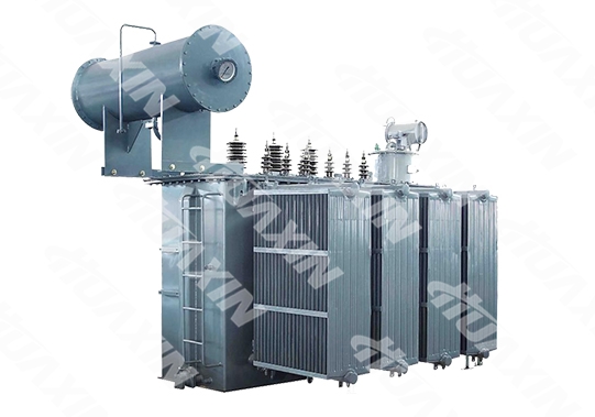
The 35KV Three-phase Oil-immersed Power Transformer adopts a high-quality cold-rolled silicon steel sheet and ladder three-stage seam,.The surface is coated with curing paint, which effectively reduces loss and noise; the coil is wound with high-quality oxygen-free copper conductor, the novel oil duct structure with reasonable design is adopted for radiation, which optimizes the insulation process, improves mechanical strength and anti-short circuit ability. It has artistic and generous outline, and is widely used in the transformer substations (stations), and urban and rural power grids.
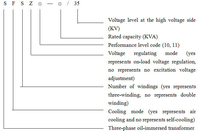
Model Description:
Technical Parameters:
1. Rated Capacity: see Table 1, Table 2 and Table 3:
2. Rated Voltage: see Table 1, Table 2 and Table 3:
3. Rated Frequency 50 Hz
4. Number of Phases: 3 phases;
5. Cooling Mode; oil-immersed natural cooling(ONAN);
6. Temperature Resistance Level of the Insulation Materials: Level A;
7. Technical Performance Data and Coupling Group Number: see Table 1, Table 2 and Table 3.
Table 1 Double Windings No Excitation Voltage Adjustment Distribution Transformer
Rated Capacity (kVA) | Voltage Combination (kV) | Coupling Group | No-load Loss (W) | Load Loss (W) (75℃) | Short-circuit Impedance (%) | No-load Current (%) |
| ||
High-voltage (KV) | Tapping (%) | Low-voltage (KV) |
| ||||||
50 | 35 38.5 | ±5 | 0.4 | Dyn11 Yyn0 | 160 | 1200/1140 | 6.5 | 1.6 | 1.3 |
100 | 230 | 2010/1910 | 1.4 | 1.1 | |||||
125 | 270 | 2370/2260 | 1.4 | 1.1 | |||||
160 | 280 | 2820/2680 | 1.3 | 1 | |||||
200 | 340 | 3320/3160 | 1.2 | 1 | |||||
250 | 400 | 3950/3760 | 1.1 | 0.95 | |||||
315 | 480 | 4750/4530 | 1.1 | 0.95 | |||||
400 | 580 | 5740/5470 | 1 | 0.85 | |||||
500 | 680 | 6910/6580 | 1 | 0.85 | |||||
630 | 830 | 7860 | 0.9 | 0.65 | |||||
800 | 980 | 9400 | 0.8 | 0.65 | |||||
1000 | 1150 | 11500 | 0.8 | 0.65 | |||||
1250 | 1400 | 13900 | 0.7 | 0.6 | |||||
1600 | 1690 | 16600 | 0.6 | 0.6 | |||||
Note: for the transformer with the rated capacity of 500KV and below, the load loss above the slash in the table is only applicable for Dyn11 connection group, and the load loss value below the slash is applicable for Yyn0 connection group.
Table 2 Double Windings No Excitation Voltage Adjustment Distribution Transformer
Rated Capacity (kVA) | Voltage Combination (kV) | Coupling Group | Idle Load Loss (W) | Load Loss (W) (75℃) | Short-circuit Impedance (%) | No-load Current (%) |
| ||
High-voltage (KV) | Tapping (%) | Low-voltage (KV) |
| ||||||
800 | 35 | ±2×2.5 | 3.15 6.3 10.5 | Yd11 | 980 | 9400 | 6.5 | 0.8 | 0.65 |
1000 | 1150 | 11500 | 0.8 | 0.65 | |||||
1250 | 1400 | 13900 | 0.72 | 0.55 | |||||
1600 | 1690 | 16600 | 0.64 | 0.45 | |||||
2000 | 2170 | 18300 | 0.56 | 0.45 | |||||
2500 | 2500 | 19600 | 0.48 | 0.45 | |||||
3150 | 35~38.5 | 3040 | 23000 | 7 | 0.45 | 0.45 | |||
4000 | 3610 | 27300 | 0.45 | 0.45 | |||||
5000 | 4320 | 31300 | 0.38 | 0.45 | |||||
6300 | 5240 | 35000 | 7.5 | 0.38 | 0.45 | ||||
8000 | ±2×2.5 | 3.5 | YNd11 | 7200 | 38400 | 0.34 | 0.35 | ||
10000 | 8700 | 45300 | 0.34 | 0.35 | |||||
12500 | 10000 | 53800 | 8 | 0.32 | 0.3 | ||||
16000 | 12100 | 65800 | 0.32 | 0.3 | |||||
20000 | 14400 | 79500 | 0.32 | 0.3 | |||||
Note: for the transformer with low voltage of 10.5KV, the product with coupling group grade of Dyn11 can be provided.
Table 3 Double Windings on-load-tap-changing Transformer
Rated Capacity (kVA) | Voltage Combination (kV) | Coupling Group | Idle Load Loss (W) | Load Loss (W) (75℃) | Short-circuit Impedance (%) | No-load Current (%) |
| ||
High-voltage (KV) | Tapping (%) | Low-voltage (KV) |
| ||||||
2000 | 35 | ±3×2.5 | 6.3 10.5 | Yd11 | 2300 | 19200 | 6.5 | 0.64 | 0.5 |
2500 | 2720 | 20600 | 0.64 | 0.5 | |||||
3150 | 35~38.5 | 3230 | 24700 | 7 | 0.58 | 0.5 | |||
4000 | 3870 | 29100 | 0.58 | 0.5 | |||||
5000 | 4640 | 34200 | 0.54 | 0.5 | |||||
6300 | 5630 | 36700 | 8 | 0.54 | 0.5 | ||||
8000 | 6.3 | YNd11 | 7870 | 40600 | 0.48 | 0.4 | |||
10000 | 9280 | 48000 | 0.48 | 0.4 | |||||
12500 | 10900 | 56800 | 0.45 | 0.35 | |||||
16000 | 13100 | 70300 | 0.43 | 0.35 | |||||
20000 | 15500 | 82700 | 0.43 | 0.35 | |||||
25000 | 18300 | 97800 | 10 | 0.4 | 0.3 | ||||
Note: for the transformer with low voltage of 10.5KV, the product with coupling group grade of Dyn11 can be provided.
The 35kV Oil-immersed Power Transformer product manufactured by our company has the features of 'four lows and one high', which are: low loss, low noise, low temperature rise, low partial discharge, and high reliability. Meanwhile, it has the features of lifting core-free, no leakage and more. The advanced design software is adopted for electromagnetic calculation, and computational analysis of main and longitudinal insulation, impulse voltage gradient distribution, end electric field distribution, short-circuit thermal stability, dynamic stable intensity, etc, so as to guarantee the design margin as well as the safe and reliable operation of the transformer. Our company has successfully manufactured multiple 35kV large-capacity 25000kVA power transformers, the market share of the product is high, and user satisfaction is good.
1. Low Loss and Low Noise:
The high-performance cold-rolled oriented silicon steel sheet is adopted for the iron core. The fully automatic cross cutting machine is employed, the small shearing burr and the low lamination coefficient can effectively reduce no-load loss, no-load current and the noise of the transformer.
2. Safe and Reliable Operation:
The sufficient margin is reserved for transformer insulation design, and the partial discharge amount is ≤ 100pC. The winding current density is reasonable, the conductor withstand stress has an appropriate margin, and the temperature rising of the transformer oil level is lower than national standards.
3. Advanced Structure and Convenient Maintenance:
a. The high-quality insulation framework is adopted in the coil for support. Both the internal and external stays are adopted for all coils, chamfer is adopted for all stays and cushion blocks, the electric field is uniform, and reliability is enhanced. The self-locking nuts are selected for all fasteners on the body, so that the product can withstand bumps during long-distance transport, be free of loosening and not requiring lifting core;
b. The wide-width steel plate is adopted for the oil tank wall to reduce seam, the unique welding process is adopted, and there is no leakage, so as to guarantee welding quality;
c. The trench structure is adopted for sealing flanges, so as to guarantee sealing performance. The copper valve is adopted for all oil drain valves, and the vacuum butterfly valve is adopted for the radiator, so as to reduce probability of leakage;
d. The transformer is installed with the oil surface thermometer. The pressure release valve with contact is installed at the top of the oil tank. The oil level gauge with contact is adopted for the oil level sign of the oil conservator. The anti-fouling enhanced pure porcelain oil bushing is adopted for the high and low voltage bushings, which can be used for the environment at heavy pollution level.
Table 1 Double Windings No Excitation Voltage Adjustment Distribution Transformer
Rated Capacity (kVA) | External Dimensions (mm) L × W × H | Weight (kg) | Gauge (mm) | ||
Machine Weight | Oil Weight | Total Weight | |||
50 | 1150×720×1200 | 230 | 320 | 680 | 550×550 |
100 | 1200×740×1300 | 380 | 400 | 980 | 550×550 |
125 | 1250×780×1380 | 440 | 430 | 1100 | 550×550 |
160 | 1300×800×1400 | 510 | 460 | 1200 | 660×660 |
200 | 1400×840×1500 | 620 | 500 | 1400 | 660×660 |
250 | 1530×860×1580 | 690 | 530 | 1500 | 660×660 |
315 | 1600×890×1630 | 820 | 570 | 1680 | 660×660 |
400 | 1730×950×1700 | 930 | 650 | 1950 | 660×660 |
500 | 1800×980×1800 | 1070 | 710 | 2300 | 820×820 |
630 | 1900×1000×1850 | 1320 | 830 | 2650 | 820×820 |
800 | 1950×1060×1900 | 1570 | 900 | 3100 | 820×820 |
1000 | 1980×1100×1950 | 1800 | 1080 | 3750 | 820×820 |
1250 | 2010×1160×1980 | 2100 | 1150 | 4050 | 820×820 |
1600 | 2040×1310×2000 | 2550 | 1250 | 4730 | 820×820 |
Table 2 Double Windings No Excitation Voltage Transformer
Rated Capacity (kVA) | External Dimensions (mm) L × W × H | Weight (kg) | Gauge (mm) | ||
Machine Weight | Oil Weight | Total Weight | |||
800 | 2020×1360×2400 | 1510 | 890 | 3250 | 820×820 |
1000 | 2180×1380×2550 | 2060 | 1040 | 3780 | 1070×1070 |
1250 | 2220×1300×2520 | 2150 | 1090 | 3890 | 1070×1070 |
1600 | 2270×1340×2450 | 2430 | 1140 | 4450 | 1070×1070 |
2000 | 2250×1380×2210 | 2820 | 1420 | 5670 | 1070×1070 |
2500 | 2300×1400×2300 | 3330 | 1550 | 6100 | 1070×1070 |
3150 | 2520×2720×2550 | 3670 | 1630 | 7100 | 1070×1070 |
4000 | 2800×2250×2500 | 4500 | 1830 | 8250 | 1070×1070 |
5000 | 3000×2370×2800 | 5255 | 1900 | 9120 | 1070×1070 |
6300 | 2830×3020×2920 | 6650 | 2250 | 11200 | 1070×1070 |
8000 | 3300×2970×3050 | 9470 | 3160 | 15200 | 1475×1475 |
10000 | 3250×2850×3000 | 10180 | 3050 | 17000 | 1475×1475 |
12500 | 3500×2930×3500 | 11000 | 3660 | 18800 | 1475×1475 |
16000 | 3620×3040×3600 | 13650 | 4250 | 22200 | 1475×1475 |
20000 | 3900×3650×3540 | 15200 | 5250 | 26750 | 1475×1475 |
Table 3 Double Windings on-load tap Changing Transformer
Rated Capacity (kVA) | External Dimensions (mm) L × W × H | Weight (kg) | Gauge (mm) | ||
Machine Weight | Oil Weight | Total Weight | |||
2000 | 2600×1800×2785 | 3100 | 1800 | 6100 | 1475×1475 |
2500 | 2700×1900×2970 | 3570 | 1850 | 7000 | 1475×1475 |
3150 | 3390×2170×3040 | 4805 | 2575 | 8850 | 1475×1475 |
4000 | 3100×3000×3150 | 4470 | 2320 | 9250 | 1475×1475 |
5000 | 3100×3000×3450 | 5550 | 2550 | 10800 | 1475×1475 |
6300 | 3320×3350×2980 | 6450 | 2860 | 12300 | 1475×1475 |
8000 | 3470×3130×3550 | 7970 | 3150 | 14720 | 1475×1475 |
10000 | 4596×3670×3735 | 10250 | 5275 | 20655 | 1475×1070 |
12500 | 4945×3550×3720 | 13385 | 5985 | 24185 | 1475×1475 |
16000 | 4940×3550×4457 | 14690 | 7025 | 27835 | 1475×1475 |
20000 | 4950×3945×4025 | 17250 | 7565 | 31325 | 1475×1475 |
25000 | 5100×3640×4220 | 20995 | 8530 | 36510 | 1475×1475 |
Note: the external dimensions shall be subject to actual dimensions of the transformer.
1. Iron Core: 30Q130 high permeability silicon steel sheet is used. The advanced step multi-laminated mode is adopted to effectively reduce no-load loss, no-load current and noise;
2. Winding: the oxygen-free copper conductor with high electric conductivity is adopted as the electromagnetic wire, and the new process of overall package of the cylinder type, double pie type and novel screw type is adopted for winding, so that the product structure is more compact. Main insulation can be effectively guaranteed, the first and tail layers are reinforced, and insulation property is improved. The outer surface of winding is wound with high-strength shrinkable tape, which improves its mechanical strength, and greatly improves its impact resistance and anti-short circuit ability;
3. Body: the body insulation pad is supported with the high-strength laminated wood and laminated paper board, so that the supporting area at the winding end reached over 95%, so as to further improve product anti-short circuit ability and operation reliability. The stiff belt buffer structure is adopted for connection between the body and the box cover, so as to overcome the phenomena of 'suspension' and 'the cover pressing'. The insulation material is wrapped with the high-strength and high-density cable paper, and the allowed pressure is 45MPa;
4. Oil Tank: the radiating pipe is adopted for the oil tank (the piece inserting method is adopted for the double-row and three-row oil pipes), or the ladder finned radiator is adopted, so as to increase the heat-dissipating capability in the same tank wall area; the finned radiator or corrugated tank and the forced oil air cooling or forced oil water cooling heat sink shall also be installed according to users' requirements. 'Conformal coating' (salt fog proof, high temperature-resistant, and mould proof) is used for the surface treatment of the oil tank, the adhesion force of the top coat and the primer is strong, decoration is good, the thin film oil resistance, corrosion resistance, gloss retention and color retention are good, and it has good leveling property and covering power;
5. Chosen Components: the pressure relief valve, signal thermometer, gas relay and more are installed according to the standard requirements, so as to guarantee a safe operation of the transformer;
6. The series products have an artistic appearance and small sizes, which can reduce the floor area for installation, and are the ideal maintenance-free high-quality ones.
Meanwhile, we make many improvements based on traditional structure and mature technology, such as: helical winding with longitudinal oil duct, better internal radiation; improved effective support of the coil end surface, and stronger resistance to short-circuit current; the new lifting structure and body positioning structure are adopted to make it more reliable for long-distance transport and operation.
1. Maximum temperature: +40℃/+104ºF;
2. Maximum daily average temperature: +30℃/+84ºF;
3. Maximum annual average temperature: +20℃/+68ºF;
4. Minimum temperature: -45℃/-49ºF;
5. Elevation shall not exceed 1000m;
6. Indoor or outdoor use.
Note: please make specific instructions in case of any special use conditions.
Close
Close


©1996-2023 晋ICP备07500050号 Huaxin Copyright


©1996-2023 晋ICP备07500050号 Huaxin Copyright